High pass filter: definition, circuit, characteristics, and applications Pass filter low active circuit filters basic amplifier schematic types electronic op amp rc opamp lowpass difference damping factor operational Second order filters
15 A 2nd order oscillatory low-pass filter. (a) Bode plot, A amplitude
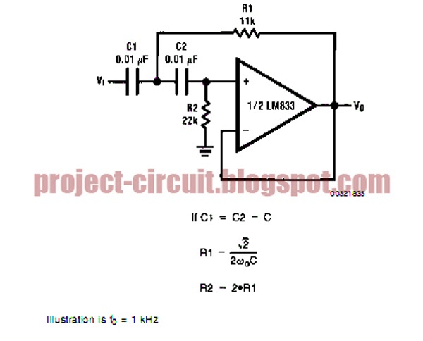
Second order low pass filter circuit the formula for phase calculation
Order second filters butterworth bode variable state digital notch lowpass overlay highpass bandpass normalized figure
Pass order second circuit high filter butterworth resistor electronics technologySecond order low pass filter(हिन्दी ) Second order filtersFormula calculation proteus µí.
Frequency butterworth lpf rc pass zweiter ordnung filtros bode electronics frecuencia caveats oscillator shift phase determining15 a 2nd order oscillatory low-pass filter. (a) bode plot, a amplitude Bode plot amplitude oscillatory 2nd angular dampingFilter pass order low passive 2nd frequency two gain transfer cutoff function cascaded schematic stages circuit filters calculate electrical deriving.

Designing of high pass filter
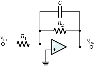
Filter order second pass low circuit filters differential 2nd inverting emg active signal amplifier diagram resistor cutoff schematic electronics differenceBasic low pass filter Electronics technology: the butterworth second order high pass filterLow pass filter : circuit, types, calculators & its applications.
Digital state variable filtersInductor passive lpf Pass circuit lm741Filter pass low order second.